


Ultra High Precision MZM modulator Bias Controller Automatic Bias Controller


Feature
• Bias voltage control on Peak/Null/Q+/Q−
• Bias voltage control on arbitrary point
• Ultra precise control: 50dB maximum extinction ratio on Null mode;
±0.5◦ accuracy on Q+ and Q− modes
• Low dither amplitude:
0.1% Vπ at NULL mode and PEAK mode
2% Vπ at Q+ mode and Q− mode
• High stability: with fully digital implementation
• Low profile: 40mm(W) × 30mm(D) × 10mm(H)
• Easy to use: Manual operation with mini jumper;
Flexible OEM operations through MCU UART2
• Two different modes to provide bias voltage: a.Automatic bias control
b. User defined bias voltage
Application
• LiNbO3 and other MZ modulators
• Digital NRZ, RZ
• Pulse applications
• Brillouin scattering system and other optical sensors
• CATV Transmitter
Performance
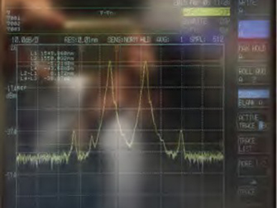
Figure 1. Carrier Supression
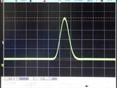
Figure 2. Pulse Generation
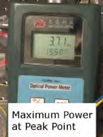
Figure 3. Modulator max power
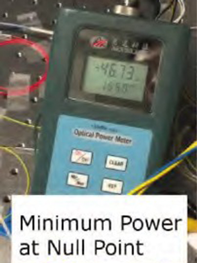
Figure 4. Modulator minimum power
Maxim DC extinction ratio
In this experiment, no RF signals were applied to the system. Pure DC extinciton has been measured.
1. Figure 5 demonstrates the optical power of modulator output, when modulator controlled at Peak point. It shows 3.71dBm in the diagram.
2. Figure 6 shows the optical power of modulator output, when modulator controlled at Null point. It shows -46.73dBm in the diagram. In real experiment, the value varies around -47dBm; and -46.73 is a stable value.
3. Therefore, the stable DC extinction ratio measured is 50.4dB.
Requirements for high extinction ratio
1. System modulator must have high extinction ratio. Characteristic of system modulator decides the maximum extinction ratio can be achieved.
2. Polarization of modulator input light shall be taken care of. Modulators are sensitive to polarization. Proper polarization can improve extinction ratio over 10dB. In lab experiments, usually a polarization controller is needed.
3. Proper bias controllers. In our DC extinction ratio experiment, 50.4dB extinction ratio has been achieved. While the datasheet of the modulator manufacture only lists 40dB. The reason of this improvement is that some modulators drift very fast. Rofea R-BC-ANY bias controllers update the bias voltage every 1 second to ensure fast track response.
Specifications
| Parameter |
Min |
Typ |
Max |
Unit |
Conditions |
| Control Performance | |||||
| Extinction ratio |
MER 1 |
50 |
dB |
||
| CSO2 |
−55 |
−65 |
−70 |
dBc |
Dither amplitude: 2%Vπ |
| Stablization time |
4 |
s |
Tracking points: Null & Peak | ||
|
10 |
Tracking points: Q+ & Q- | ||||
| Electrical | |||||
| Positive power voltage |
+14.5 |
+15 |
+15.5 |
V |
|
| Positive power current |
20 |
30 |
mA |
||
| Negative power voltage |
-15.5 |
-15 |
-14.5 |
V |
|
| Negative power current |
2 |
4 |
mA |
||
| Output voltage range |
-9.57 |
+9.85 |
V |
||
| Output voltage precision |
346 |
µV |
|||
| Dither frequency |
999.95 |
1000 |
1000.05 |
Hz |
Version: 1kHz dither signal |
| Dither amplitude |
0.1%Vπ |
V |
Tracking points: Null & Peak | ||
| 2%Vπ | Tracking points: Q+ & Q- | ||||
| Optical | |||||
| Input optical power3 |
-30 |
-5 |
dBm |
||
| Input wavelength |
780 |
2000 |
nm |
||
1. MER refers to Modulator Extinction Ratio. The extinction ratio achieved is typically the extinction ratio of modulator specified in modulator datasheet.
2. CSO refers to composite second order. To measure CSO correctly, the linear quality of RF signal, modulators and receivers shall be ensured. In addition, the system CSO readings may vary when running at different RF frequencies.
3. Please be noted that input optical power does not correspond to the optical power at selected bias point. It refers to the maximum optical power that the modulator can export to controller when bias voltage ranges from −Vπ to +Vπ .
User Interface
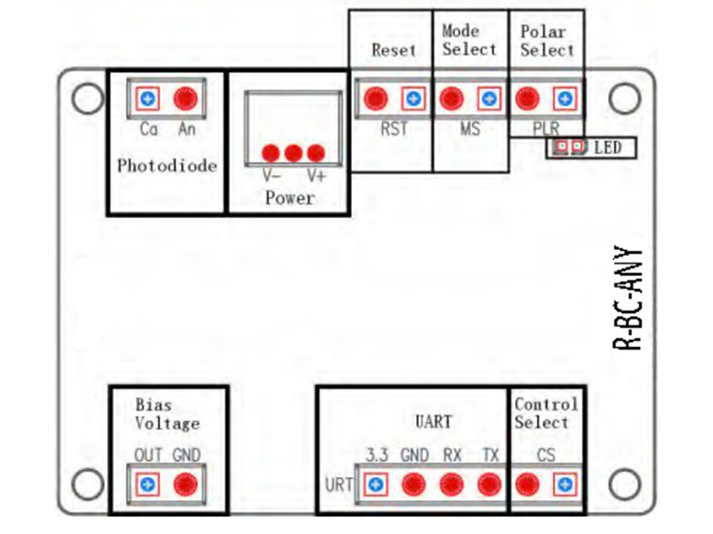
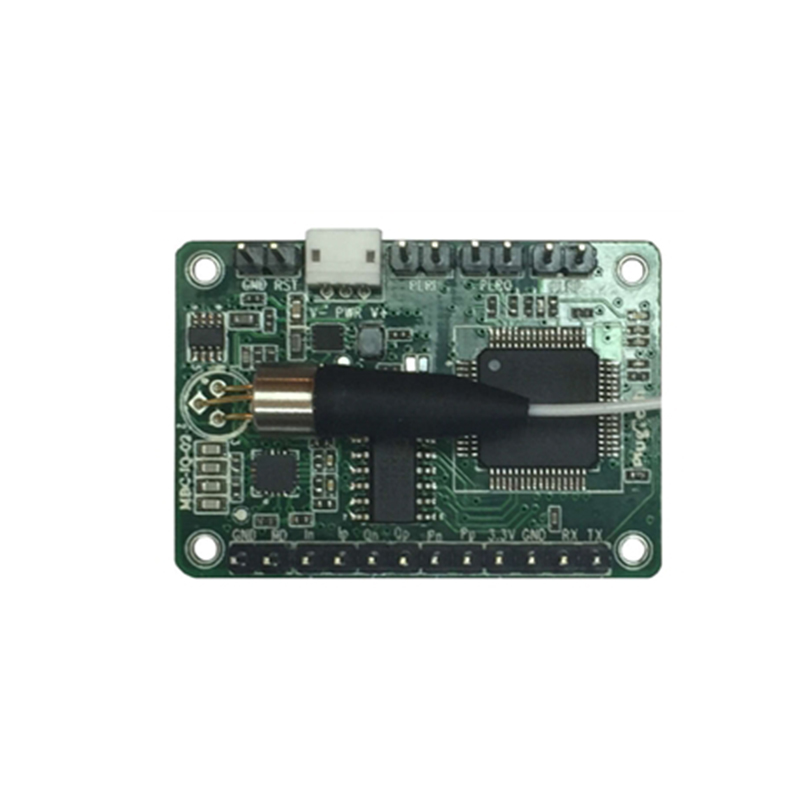
Figure5. Assembly
| Group |
Operation |
Explanation |
| Photodiode 1 | PD: Connect MZM photodiode’s Cathode | Provide photocurrent feedback |
| GND: Connect MZM photodiode’s Anode | ||
| Power | Power source for bias controller | V-: connects the negative electrode |
| V+: connects the positive electrode | ||
| Middle probe: connects the ground electrode | ||
| Reset | Insert jumper and pull out after 1 second | Reset the controller |
| Mode Select | Insert or pull out the jumper | no jumper: Null mode; with jumper: Quad mode |
| Polar Select2 | Insert or pull out the jumper | no jumper: Positive Polar; with jumper: Negative Polar |
| Bias Voltage | Connect with the MZM bias voltage port | OUT and GND provide bias voltages for modulator |
| LED | Constrantly on | Working under stable state |
| On-off or off-on every 0.2s | Processing data and searching for controlling point | |
| On-off or off-on every 1s | Input optical power is too weak | |
| On-off or off-on every 3s | Input optical power is too strong | |
| UART | Operate controller via UART | 3.3: 3.3V reference voltage |
| GND: Ground | ||
| RX: Receive of controller | ||
| TX: Transmit of controller | ||
| Control Select | Insert or pull out the jumper | no jumper: jumper control;with jumper:UART control |
1. Some MZ modulators have internal photodiodes. Controller setup should be chosen between using controller’s photodiode or using modulator’s internal photodiode. It is recommended to use controller’s photodiode for Lab experiments for two reasons. Firstly, controller photodiode has ensured quality. Secondly, it is easier to adjust the input light intentsity. Note: If using modulator’s internal photodiode, please make sure that the output current of photodiode is strictly proportional to input power.
2. Polar pin is used to switch the control point between Peak and Null in Null control mode(determined by Mode Select pin) or Quad+
and Quad- in Quad control mode. If jumper of polar pin is not inserted, the control point will be Null in Null mode or Quad+ in Quad mode. Amplitude of RF system will also affect the control point. When there is no RF signal or RF signal amplitude is small, controller is able to lock the work point to correct point as selected by MS and PLR jumper. When the RF signal amplitude exceeds certain threshold, polar of the system will be changed, in this case, the PLR header should be in the opposite state, i.e. the jumper should be inserted if it is not or pulled out if it is inserted.
Typical Application
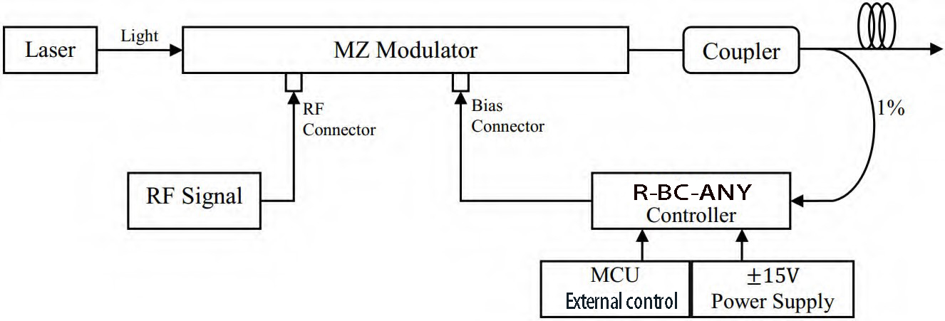
The controller is easy to use.
Step1. Connect 1% port of the coupler to the photodiode of the controller.
Step2. Connect bias voltage output of the controller(through SMA or 2.54mm 2-pin header) to bias port of the modulator.
Step3. Provide controller with +15V and -15V DC voltages.
Step4. Reset the controller and it will start to work.
NOTE. Please be ensured that RF signal of the whole system is on before resetting the controller.
Rofea Optoelectronics offers a product line of commercial Electro-optic modulators, Phase modulators, Intensity modulator, Photodetectors, Laser light sources, DFB lasers,Optical amplifiers, EDFA, SLD laser, QPSK modulation, Pulse laser, Light detector, Balanced photodetector, Laser driver, Fiber optic amplifier, Optical power meter, Broadband laser, Tunable laser, Optical detector, Laser diode driver, Fiber amplifier. We also provide many particular modulators for customization, such as 1*4 array phase modulators, ultra-low Vpi, and ultra-high extinction ratio modulators, primarily used in universities and institutes.
Hope our products will be helpful to you and your research.

