


1. Erbium-doped fiber
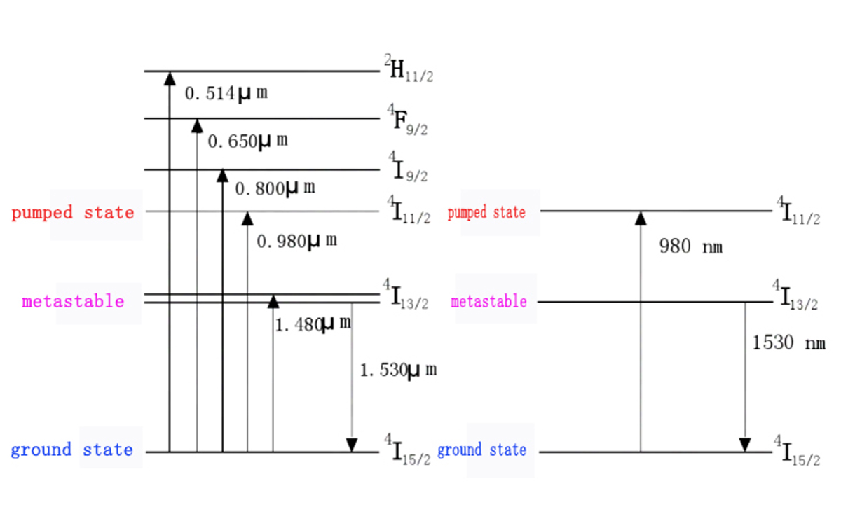
Erbium is a rare earth element with an atomic number of 68 and an atomic weight of 167.3. The erbium ion's electronic energy level is shown in the figure, and the transition from the lower energy level to the upper energy level corresponds to the absorption process of light. The change from the upper energy level to the lower energy level corresponds to the light emission process.
2. EDFA principle
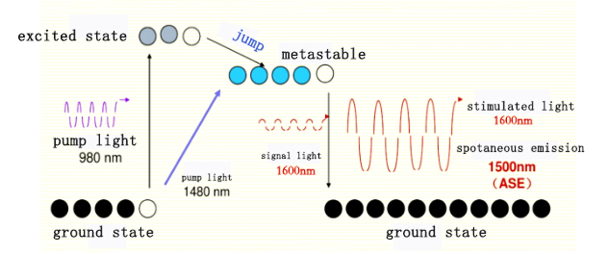
EDFA uses erbium ion-doped fiber as the gain medium, which produces population inversion under pump light. It realizes stimulated radiation amplification under the induction of signal light.
Erbium ions have three energy levels. They are at the lowest energy level, E1, when they are not excited by any light. When the fiber is continuously excited by the pump light source laser, the particles in the ground state gain energy and transition to a higher energy level. Such as the transition from E1 to E3, because the particle is unstable at the high energy level of E3, it will quickly fall to the metastable state E2 in a non-radiative transition process. At this energy level, the particles have a relatively long survival life. Due to the continuous excitation of the pump light source, the number of particles at the E2 energy level will continue to increase, and the number of particles at the E1 energy level will increase. In this way, the population inversion distribution is realized in the erbium-doped fiber, and the conditions for learning optical amplification are available.
When the input signal photon energy E=hf is precisely equal to the energy level difference between E2 and E1, E2-E1=hf, the particles in the metastable state will transition to the ground state E1 in the form of stimulated radiation. The radiation and the input The photons in the signal are identical to the photons, thus significantly increasing the photons' number, making the input optical signal become a strong output optical signal in the erbium-doped fiber, realizing the direct amplification of the optical signal.
2. System diagram and basic device introduction
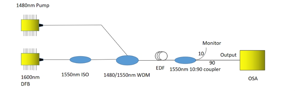
2.1. The schematic diagram of the L-band optical fiber amplifier system is as follows:
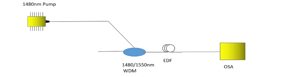
2.2. The schematic diagram of the ASE light source system for spontaneous emission of erbium-doped fiber is as follows:
Device introduction
1.ROF -EDFA -HP High Power Erbium Doped Fiber Amplifier
| Parameter | Unit | Min | Typ | Max | |
| Operating wavelength range | nm | 1525 | 1565 | ||
| Input signal power range | dBm | -5 | 10 | ||
| Saturation output optical power | dBm | 37 | |||
| Saturation output optical power stability | dB | ±0.3 | |||
| Noise index @ input 0dBm | dB | 5.5 | 6.0 | ||
| Input optical isolation | dB | 30 | |||
| Output optical isolation | dB | 30 | |||
| Input return loss | dB | 40 | |||
| Output return loss | dB | 40 | |||
| Polarization dependent gain | dB | 0.3 | 0.5 | ||
| Polarization mode dispersion | ps | 0.3 | |||
| Input pump leak | dBm | -30 | |||
| Output pump leak | dBm | -30 | |||
| Operating voltage | V( AC ) | 80 | 240 | ||
| Fiber type |
SMF-28 |
||||
| Output interface |
FC/APC |
||||
| Communication interface |
RS232 |
||||
| Package size | Module | mm |
483×385×88(2U rack) |
||
| Desktop | mm |
150×125×35 |
|||
2.ROF -EDFA -B erbium-doped fiber power amplifier
|
Parameter |
Unit |
Min |
Typ |
Max |
||
| Operating wavelength range |
nm |
1525 |
1565 |
|||
| Output signal power range |
dBm |
-10 |
||||
| Small signal gain |
dB |
30 |
35 |
|||
| Saturation optical output range * |
dBm |
17/20/23 |
||||
| Noise figure ** |
dB |
5.0 |
5.5 |
|||
| Input isolation |
dB |
30 |
||||
| Output isolation |
dB |
30 |
||||
| Polarization independent gain |
dB |
0.3 |
0.5 |
|||
| Polarization mode dispersion |
ps |
0.3 |
||||
| Input pump leak |
dBm |
-30 |
||||
| Output pump leak |
dBm |
-40 |
||||
| Operating voltage |
module |
V |
4.75 |
5 |
5.25 |
|
|
desktop |
V( AC ) |
80 |
240 |
|||
| Optical fiber |
SMF-28 |
|||||
| Output interface |
FC/APC |
|||||
| Dimensions |
module |
mm |
90×70×18 |
|||
|
desktop |
mm |
320×220×90 |
||||
3. ROF -EDFA -P model Erbium doped fiber amplifier
|
Parameter |
Unit |
Min |
Typ |
Max |
|
| Operating wavelength range |
nm |
1525 |
1565 |
||
| Input signal power range |
dBm |
-45 |
|||
| Small signal gain |
dB |
30 |
35 |
||
| Saturation optical power output range * |
dBm |
0 |
|||
| Noise index ** |
dB |
5.0 |
5.5 |
||
| Input optical isolation |
dB |
30 |
|||
| Output optical isolation |
dB |
30 |
|||
| Polarization dependent gain |
dB |
0.3 |
0.5 |
||
| Polarization mode dispersion |
ps |
0.3 |
|||
| Input pump leak |
dBm |
-30 |
|||
| Output pump leak |
dBm |
-40 |
|||
| Operating Voltage |
Module |
V |
4.75 |
5 |
5.25 |
|
Desktop |
V( AC ) |
80 |
240 |
||
| Fiber type |
SMF-28 |
||||
| Output Interface |
FC/APC |
||||
| Package size |
Module |
mm |
90*70*18 |
||
|
Desktop |
mm |
320*220*90 |
|||