


To meet people's increasing demand for information, the transmission rate of optical fiber communication systems is increasing day by day. The future optical communication network will develop towards an optical fiber communication network with ultra-high speed, ultra-large capacity, ultra-long distance, and ultra-high spectrum efficiency. A transmitter is critical. The high-speed optical signal transmitter is mainly composed of a laser that generates an optical carrier, a modulating electrical signal generating device, and a high-speed electro-optical modulator that modulates the optical carrier. Compared with other types of external modulators, lithium niobate electro-optical modulators have the advantages of wide operating frequency, good stability, high extinction ratio, stable working performance, high modulation rate, small chirp, easy coupling, mature production technology, etc. It is widely used in high-speed, large-capacity, and long-distance optical transmission systems.
The half-wave voltage is a highly critical physical parameter of the electro-optic modulator. It represents the change in the bias voltage corresponding to the output light intensity of the electro-optic modulator from the minimum to the maximum. It determines the electro-optic modulator to a large extent. How to accurately and quickly measure the half-wave voltage of the electro-optic modulator is of great significance for optimizing the device's performance and improving efficiency of the device. The half-wave voltage of the electro-optic modulator includes DC (half-wave

voltage and radiofrequency) half-wave voltage. The transfer function of the electro-optic modulator is as follows:
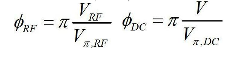
Among them is the output optical power of the electro-optic modulator;
Is the input optical power of the modulator;
Is the insertion loss of the electro-optic modulator;
Existing methods for measuring half-wave voltage include extreme value generation and frequency doubling methods, which can measure the direct current (DC) half-wave voltage and radio frequency (RF) half-wave voltage of the modulator, respectively.
Table 1 Comparison of two half-wave voltage test methods
| Extreme value method | Frequency doubling method | |
|
Laboratory equipment |
Laser power supply
Intensity modulator under test Adjustable DC power supply ±15V Optical power meter |
Laser light source
Intensity modulator under test Adjustable DC power supply Oscilloscope signal source (DC Bias) |
|
testing time |
20min() | 5min |
|
Experimental advantages |
easy to accomplish | Relatively accurate test
Can obtain DC half-wave voltage and RF half-wave voltage at the same time |
|
Experimental disadvantages |
Long time and other factors, the test is not accurate
Direct passenger test DC half-wave voltage |
Relatively long time
Factors such as large waveform distortion judgment error, etc., the test is not accurate |
It works as follows:
(1) Extreme value method
The extreme value method is used to measure the DC half-wave voltage of the electro-optic modulator. First, without the modulation signal, the transfer function curve of the electro-optic modulator is obtained by measuring the DC bias voltage and the output light intensity change, and from the transfer function curve Determine the maximum value point and the minimum value point, and obtain the corresponding DC voltage values Vmax and Vmin respectively. Finally, the difference between these two voltage values is the half-wave voltage Vπ=Vmax-Vmin of the electro-optic modulator.
(2) Frequency doubling method
It was using the frequency doubling method to measure the RF half-wave voltage of the electro-optic modulator. Add the DC bias computer and AC modulation signal to the electro-optic modulator at the same time to adjust the DC voltage when the output light intensity is changed to a maximum or minimum value. At the same time, and it can be observed on the dual-trace oscilloscope that the output modulated signal will appear frequency doubling distortion. The only difference of the DC voltage corresponding to two adjacent frequency doubling distortions is the RF half-wave voltage of the electro-optic modulator.
Summary: Both the extreme value method and the frequency doubling method can theoretically measure the half-wave voltage of the electro-optic modulator, but for comparison, the powerful value method requires a longer measurement time, and the longer measurement time will be due to The output optical power of the laser fluctuates and causes measurement errors. The extreme value method needs to scan the DC bias with a small step value and record the output optical power of the modulator at the same time to obtain a more accurate DC half-wave voltage value.
The frequency doubling method is a method of determining the half-wave voltage by observing the frequency doubling waveform. When the applied bias voltage reaches a particular value, frequency multiplication distortion occurs, and the waveform distortion is not too noticeable. It is not easy to observe with the naked eye. In this way, it will inevitably cause more significant errors, and what it measures is the RF half-wave voltage of the electro-optic modulator.