


How to use the EO modulator
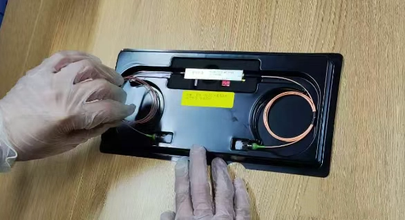
After receiving the EO modulator and opening the package, please wear electrostatic gloves/wristbands when touching the metal tube shell part of the device. Use tweezers to remove the optical input/output ports of the device from the grooves of the box, and then remove the main body of the modulator from the sponge grooves. Then hold the main body of the EO modulator in one hand and drag the optical input/output port of the modulator with the other.
Preparation and inspection before use
a. Observe that there is no damage to the product surface, module surface and optical fiber sleeve.
b. Check that the label is free from dirt and the silk-screen printing marks are clear.
c. The electric flange is undamaged and all electrode pins are intact.
d. Use an optical fiber end face detector to check whether the optical fibers at both ends are clean.
1. Steps for using intensity modulator
a. Check whether the end faces of the input/output optical fibers of the intensity modulator are clean. If there are stains, please wipe them clean with alcohol.
b. The intensity modulator is a polarization-maintaining input. It is recommended to use a polarization-maintaining light source when in use (the wavelength of the light source depends on the applicable wavelength of the modulator), and the light power of the light source is preferably 10dBm.
When using the strength modulator, connect the power supply GND to pin 1 of the modulator, and the positive terminal of the power supply to pin 2. Pin 3/4 is the cathode and anode of the PD inside the modulator. If you need to use it, please use this PD with the acquisition circuit at the back end, and this PD can be used without applying voltage (if the modulator does not have an internal PD, pin 3/4 is NC, a suspended pin).
d. The material of the intensity modulator is lithium niobate. When an electric field is applied, the refractive index of the crystal will change. Therefore, when a voltage is applied to the modulator, the insertion loss of the modulator will vary with the applied voltage. Users can control the modulator at a certain operating point according to their usage.
Precautions
a. The optical input of the modulator must not exceed the calibration value on the test sheet; otherwise, the modulator will be damaged.
b. The RF input of the modulator must not exceed the calibrated value on the test sheet; otherwise, the modulator will be damaged.
c. The added voltage of the modulator bias voltage pin is ≤±15V
2. Steps for using the phase modulator
a. Check whether the end faces of the input/output optical fibers of the intensity modulator are clean. If there are stains, please wipe them clean with alcohol.
b. The phase modulator is a polarization-maintaining input. It is recommended to use a polarization-maintaining light source when in use (the wavelength of the light source depends on the applicable wavelength of the modulator), and the light power of the light source is preferably 10dBm.
c. When using a phase modulator, connect the RF signal to the RF input port of the modulator.
d. The phase modulator can work after adding a radio frequency signal, completing the phase electro-optic modulator. The modulated light cannot be directly detected by a photodetector as the modulated radio frequency signal. Usually, an interferometer needs to be set up, and the radio frequency signal can only be detected by a photodetector after interference.
Precautions
a. The optical input of the EO modulator must not exceed the calibration value on the test sheet; otherwise, the modulator will be damaged.
b. The RF input of the EO modulator must not exceed the calibrated value on the test sheet; otherwise, the modulator will be damaged.
c. When setting up an interferometer, there are relatively high requirements for the usage environment. Environmental shaking and optical fiber swaying can both affect the test results.
Post time: Jul-29-2025