


Analysis of System Errors of Photodetector
Introduction to the Influencing Factors of System Errors in Photodetector
The specific considerations for systematic error include: 1. Component selection: photodiodes, operational amplifiers, resistors, capacitors, ADCs, power supply ics, and reference voltage sources. 2. Working environment: The influence of temperature and humidity, etc. 3. System reliability: System stability, EMC performance.
System Error Analysis of Photodetectors
1. Photodiode: In a photoelectric detection system, the influence of photodiodes on the errors of the photoelectric system is mainly manifested in the following aspects:
(1) Sensitivity (S)/ Resolution: The ratio of the output signal (voltage/current) increment △y to the input increment △x that causes the output increment △y. That is, s=△y/△x. Sensitivity/resolution is the primary condition for sensor selection. This parameter is specifically manifested in the direct correlation of photodiodes as dark current, and in the specific manifestation of photodetectors as noise equivalent power (NEP). Therefore, the most fundamental analysis of systematic error requires that the sensitivity (S)/ resolution must be higher than the actual error requirement in order to meet the error requirements of the entire photoelectric system, as the error impact caused by the factors mentioned later also needs to be considered.
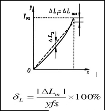
(2) Linearity (δL) : The degree of linearity of the quantitative relationship between the output and input of the photodetector. yfs is the full-scale output, and △Lm is the maximum deviation of linearity. This is specifically manifested in the linearity and linear saturation light power of the photodetector.
(3) Stability/Repeatability: The photodetector has output inconsistency for the same random input, which is a random error. The maximum deviation of the forward and reverse strokes is considered.
(4) Hysteresis: The phenomenon where the input-output characteristic curves of a photodetector do not overlap during its forward and reverse travel.
(5) Temperature drift: The influence of each 1℃ change in temperature on the output change of the photodetector. The temperature drift deviation △Tm caused by temperature drift is calculated through the temperature drift calculation of the working environment temperature range △T.
(6) Time drift: The phenomenon where the output of a photodetector changes over time when the input variable remains unchanged (the causes are mostly due to changes in its own composition structure). The comprehensive deviation influence of the photodetector on the system is calculated through vector sum.
2. Operational amplifiers: Key Parameters Affecting System error Operational Amplifiers Offset voltage Vos, Vos temperature drift, input offset current Ios, Ios temperature drift, input bias current Ib, input impedance, input capacitance, noise (input voltage noise, input current noise) Design gain thermal noise, power supply rejection ratio (PSRR), common-mode rejection ratio (CMR), open-loop gain (AoL), gain-bandwidth product (GBW), slew rate (SR), establishment time, total harmonic distortion.
Although the parameters of operational amplifiers are as important a system component as the selection of photodiodes, due to space limitations, the specific parameter definitions and descriptions will not be elaborated here. In the actual design of photodetectors, the influence of these parameters on systematic errors should all be evaluated. Although not all parameters may have a significant impact on your project requirements, depending on the actual application scenarios and different demands, the above parameters will have different effects on systematic errors.
There are many parameters for operational amplifiers. For different signal types, the main parameters causing systematic errors can be focused on DC and AC signals: DC variable signals Input offset voltage Vos, Vos temperature drift, input offset current Ios, input bias current Ib, input impedance, noise (input voltage noise, input current noise, design gain thermal noise), power supply rejection ratio (PSRR), common-mode rejection ratio (CMRR). Ac variation signal: In addition to the above parameters, the following also need to be considered: input capacitance, open-loop gain (AoL), gain-bandwidth product (GBW), slew rate (SR), establishment time, and total harmonic distortion.
Post time: Oct-10-2025