


How to reduce the noise of photodetectors
The noise of photodetectors mainly includes: current noise, thermal noise, shot noise, 1/f noise and wideband noise, etc. This classification is only a relatively rough one. This time, we will introduce more detailed noise characteristics and classifications to help everyone better understand the impact of various types of noise on the output signals of photodetectors. Only by understanding the sources of noise can we better reduce and improve the noise of photodetectors, thereby optimizing the signal-to-noise ratio of the system.
Shot noise is a random fluctuation caused by the discrete nature of charge carriers. Especially in the photoelectric effect, when photons strike photosensitive components to generate electrons, the generation of these electrons is random and conforms to the Poisson distribution. The spectral characteristics of shot noise are flat and independent of frequency magnitude, and thus it is also called white noise. Mathematical description: The root mean square (RMS) value of shot noise can be expressed as:
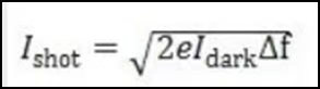
Among them:
e: Electronic charge (approximately 1.6 × 10⁻¹⁹ coulombs)
Idark: Dark current
Δf: Bandwidth
Shot noise is proportional to the magnitude of the current and is stable at all frequencies. In the formula, Idark represents the dark current of the photodiode. That is, in the absence of light, the photodiode has unwanted dark current noise. As the inherent noise at the very front end of the photodetector, the larger the dark current, the greater the noise of the photodetector. Dark current is also affected by the bias operating voltage of the photodiode, that is, the larger the bias operating voltage, the greater the dark current. However, the bias working voltage also affects the junction capacitance of the photodetector, thereby influencing the speed and bandwidth of the photodetector. Moreover, the greater the bias voltage, the greater the speed and bandwidth. Therefore, in terms of the shot noise, dark current and bandwidth performance of photodiodes, reasonable design should be carried out according to the actual project requirements.
2. 1/f Flicker Noise
1/f noise, also known as flicker noise, mainly occurs in the low-frequency range and is related to factors such as material defects or surface cleanliness. From its spectral characteristic diagram, it can be seen that its power spectral density is significantly smaller in the high-frequency range than in the low-frequency range, and for every 100 times increase in frequency, the spectral density noise linearly decreases by 10 times. The power spectral density of 1/f noise is inversely proportional to the frequency, that is:
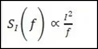
Among them:
SI(f) : Noise power spectral density
I: Current
f: Frequency
1/f noise is significant in the low-frequency range and weakens as the frequency increases. This characteristic makes it a major source of interference in low-frequency applications. 1/f noise and wideband noise mainly come from the voltage noise of the operational amplifier inside the photodetector. There are many other sources of noise that affect the noise of photodetectors, such as the power supply noise of operational amplifiers, current noise, and the thermal noise of the resistance network in the gain of operational amplifier circuits.
3. Voltage and current noise of the operational amplifier: The voltage and current spectral densities are shown in the following figure:
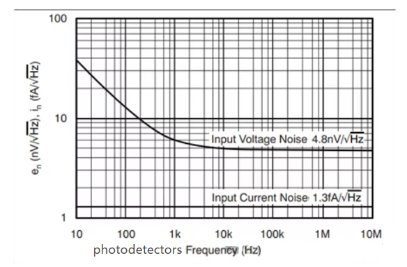
In operational amplifier circuits, current noise is divided into in-phase current noise and inverting current noise. The in-phase current noise i+ flows through the source internal resistance Rs, generating an equivalent voltage noise u1= i+*Rs. I- Inverting current noise flows through the gain equivalent resistor R to generate equivalent voltage noise u2= I-* R. So when the RS of the power supply is large, the voltage noise converted from current noise is also very large. Therefore, to optimize for better noise, the power supply noise (including internal resistance) is also a key direction for optimization. The spectral density of current noise does not change with frequency variations either. Therefore, after being amplified by the circuit, it, like the dark current of the photodiode, comprehensively forms the shot noise of the photodetector.
4. The thermal noise of the resistance network for the gain (amplification factor) of the operational amplifier circuit can be calculated using the following formula:
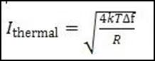
Among them:
k: Boltzmann constant (1.38 × 10⁻²³J/K)
T: Absolute Temperature (K)
R: Resistance (ohms) thermal noise is related to temperature and resistance value, and its spectrum is flat. It can be seen from the formula that the larger the gain resistance value, the greater the thermal noise. The larger the bandwidth, the greater the thermal noise will also be. Therefore, to ensure that the resistance value and bandwidth value meet both the gain requirements and the bandwidth requirements, and ultimately also demand low noise or high signal-to-noise ratio, the selection of gain resistors needs to be carefully considered and evaluated based on the actual project requirements to achieve the ideal signal-to-noise ratio of the system.
Summary
Noise improvement technology plays a significant role in enhancing the performance of photodetectors and electronic devices. High precision means low noise. As technology demands higher precision, the requirements for noise, signal-to-noise ratio, and equivalent noise power of photodetectors are also getting higher and higher.
Post time: Sep-22-2025