


Optocouplers, which connect circuits using optical signals as the medium, are an element active in areas where high precision is indispensable, such as acoustics, medicine and industry, due to their high versatility and reliability, such as durability and insulation.
But when and under what circumstances does the optocoupler work, and what is the principle behind it? Or when you actually use the photocoupler in your own electronics work, you may not know how to choose and use it. Because optocoupler is often confused with “phototransistor” and “photodiode”. Therefore, what is a photocoupler will be introduced in this article.
What is a photocoupler?
The optocoupler is an electronic component whose etymology is optical
coupler, which means “coupling with light.” Sometimes also known as optocoupler, optical isolator, optical insulation, etc. It consists of light emitting element and light receiving element, and connects input side circuit and output side circuit through optical signal. There is no electrical connection between these circuits, in other words, in a state of insulation. Therefore, the circuit connection between the input and output is separate and only the signal is transmitted. Securely connect circuits with significantly different input and output voltage levels, with high voltage insulation between input and output.
In addition, by transmitting or blocking this light signal, it acts as a switch. The detailed principle and mechanism will be explained later, but the light emitting element of the photocoupler is an LED (light emitting diode).
From the 1960s to the 1970s, when leds were invented and their technological advances were significant, optoelectronics became a boom. At that time, various optical devices were invented, and the photoelectric coupler was one of them. Subsequently, optoelectronics quickly penetrated into our lives.
① Principle/mechanism
The principle of the optocoupler is that the light-emitting element converts the input electrical signal into light, and the light-receiving element transmits the light back electrical signal to the output side circuit. The light emitting element and the light receiving element are on the inside of the block of external light, and the two are opposite each other in order to transmit light.
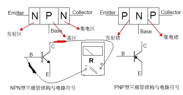
The semiconductor used in light-emitting elements is the LED (light-emitting diode). On the other hand, there are many kinds of semiconductors used in light-receiving devices, depending on the use environment, external size, price, etc., but in general, the most commonly used is the phototransistor.
When not working, phototransistors carry little of the current that ordinary semiconductors do. When the light incident there, the phototransistor generates a photoelectromotive force on the surface of the P-type semiconductor and N-type semiconductor, the holes in the N-type semiconductor flow into the p region, the free electron semiconductor in the p region flows into the n region, and the current will flow.
Phototransistors are not as responsive as photodiodes, but they also have the effect of amplifying the output to hundreds to 1,000 times the input signal (due to the internal electric field). Therefore, they are sensitive enough to pick up even weak signals, which is an advantage.
In fact, the “light blocker” we see is an electronic device with the same principle and mechanism.
However, light interrupters are usually used as sensors and perform their role by passing a light-blocking object between the light-emitting element and the light-receiving element. For example, it can be used to detect coins and banknotes in vending machines and ATMs.
② Features
Since the optocoupler transmits signals through light, the insulation between the input side and the output side is a major feature. High insulation is not easily affected by noise, but also prevents accidental current flow between adjacent circuits, which is extremely effective in terms of safety. And the structure itself is relatively simple and reasonable.
Due to its long history, the rich product lineup of various manufacturers is also a unique advantage of optocouplers. Because there is no physical contact, the wear between the parts is small, and the life is longer. On the other hand, there are also characteristics that the luminous efficiency is easy to fluctuate, because the LED will slowly deteriorate with the passing of time and temperature changes.
Especially when the internal component of the transparent plastic for a long time, become cloudy, it can not be very good light. However, in any case, the life is too long compared to the contact contact of the mechanical contact.
Phototransistors are generally slower than photodiodes, so they are not used for high-speed communications. However, this is not a disadvantage, as some components have amplification circuits on the output side to increase speed. In fact, not all electronic circuits need to increase speed.
③ Usage
Photoelectric couplers are mainly used for switching operation. The circuit will be energized by turning on the switch, but from the point of view of the above characteristics, especially insulation and long life, it is well suited to scenarios requiring high reliability. For example, noise is the enemy of medical electronics and audio equipment/communication equipment.
It is also used in motor drive systems. The reason for the motor is that the speed is controlled by the inverter when it is driven, but it generates noise due to the high output. This noise will not only cause the motor itself to fail, but also flow through the “ground” affecting peripherals. In particular, equipment with long wiring is easy to pick up this high output noise, so if it happens in the factory, it will cause great losses and sometimes cause serious accidents. By using highly insulated optocouplers for switching, the impact on other circuits and devices can be minimized.
Second, how to choose and use optocouplers
How to use the right optocoupler for application in product design? The following microcontroller development engineers will explain how to select and use optocouplers.
① Always open and always close
There are two types of photocouplers: a type in which the switch is turned off (off) when no voltage is applied, a type in which the switch is turned on (off) when a voltage is applied, and a type in which the switch is turned on when there is no voltage. Apply and turn off when voltage is applied.
The former is called normally open, and the latter is called normally closed. How to choose, first depends on what kind of circuit you need.
② Check the output current and applied voltage
Photocouplers have the property of amplifying the signal, but do not always pass through voltage and current at will. Of course, it is rated, but a voltage needs to be applied from the input side according to the desired output current.
If we look at the product data sheet, we can see a chart where the vertical axis is the output current (collector current) and the horizontal axis is the input voltage (collector-emitter voltage). The collector current varies according to the LED light intensity, so apply the voltage according to the desired output current.
However, you might think that the output current calculated here is surprisingly small. This is the current value that can still be reliably output after taking into account the deterioration of the LED over time, so it is less than the maximum rating.
On the contrary, there are cases where the output current is not large. Therefore, when choosing the optocoupler, be sure to carefully check the “output current” and choose the product that matches it.
③ Maximum current
The maximum conduction current is the maximum current value that the optocoupler can withstand when conducting. Again, we need to make sure we know how much output the project needs and what the input voltage is before we buy. Make sure that the maximum value and the current used are not limits, but that there is some margin.
④ Set the photocoupler correctly
Having chosen the right optocoupler, let’s use it in a real project. The installation itself is easy, just connect the terminals connected to each input side circuit and output side circuit. However, care should be taken not to misorient the input side and the output side. Therefore, you must also check the symbols in the data table, so that you will not find that the photoelectric coupler foot is wrong after drawing the PCB board.
Post time: Jul-29-2023