


Directional couplers are standard microwave/millimeter wave components in microwave measurement and other microwave systems. They can be used for signal isolation, separation, and mixing, such as power monitoring, source output power stabilization, signal source isolation, transmission and reflection frequency sweeping Test, etc. It is a directional microwave power divider, and it is an indispensable component in modern swept-frequency reflectometers. Usually, there are several types, such as waveguide, coaxial line, stripline, and microstrip.
Figure 1 is a schematic diagram of the structure. It mainly includes two parts, the mainline and the auxiliary line, which is coupled with each other through various forms of small holes, slits, and gaps. Therefore, part of the power input from the “1″ on the mainline end will be coupled to the secondary line. Due to the interference or superposition of waves, the power will only be transmitted along the secondary line-one direction (called “forward”), and the other There is almost no power transmission in one order (called “reverse”)
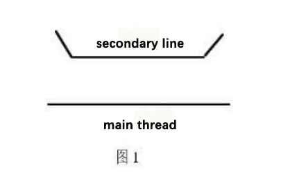
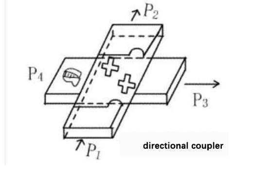
Figure 2 is a cross-directional coupler, one of the ports in the coupler is connected to a built-in matching load.
Application of Directional Coupler
1, for power synthesis system
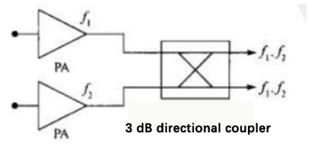
A 3dB directional coupler (commonly known as a 3dB bridge) is usually used in a multi-carrier frequency synthesis system, as shown in the figure below. This kind of circuit is common in indoor distributed systems. After the signals f1 and f2 from two power amplifiers pass through a 3dB directional coupler, the output of each channel contains two frequency components f1 and f2, and 3dB reduces the amplitude of each frequency component. If one of the output terminals is connected to an absorbing load, the other output can be used as the power source of the passive intermodulation measurement system. If you need to improve the isolation further, you can add some components such as filters and isolators. The isolation of a well-designed 3dB bridge can be more than 33dB.
The directional coupler is used in power combining system one.
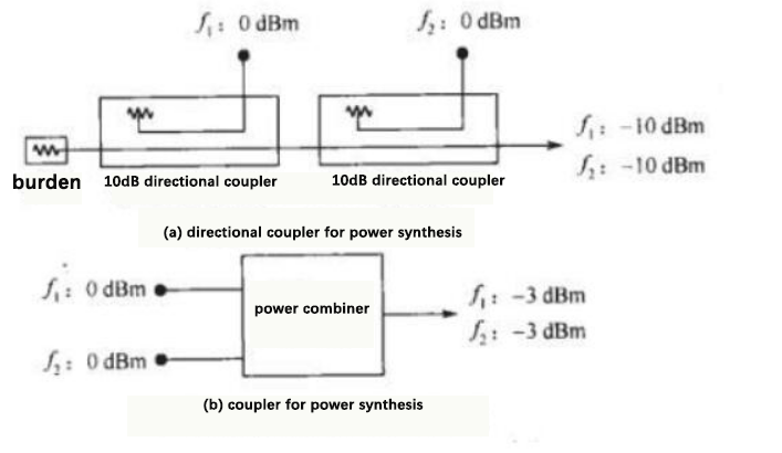
The directional gully area as another application of power combining is shown in figure (a) below. In this circuit, the directivity of the directional coupler has been cleverly applied. Assuming that the coupling degrees of the two couplers are both 10dB and the directivity is both 25dB, the isolation between the f1 and f2 ends is 45dB. If the inputs of f1 and f2 are both 0dBm, the combined output is both -10dBm. Compared with the Wilkinson coupler in figure (b) below (its typical isolation value is 20dB), the same input signal of OdBm, after synthesis, there is -3dBm (without considering the insertion loss). Compared to the inter-sample condition, we increase the input signal in figure (a) by 7dB so that its output is consistent with figure (b). At this time, the isolation between f1 and f2 in figure (a) “decreases” “Is 38 dB. The final comparison result is that the directional coupler’s power synthesis method is 18dB higher than the Wilkinson coupler. This scheme is suitable for the intermodulation measurement of ten amplifiers.
A directional coupler is used in power combining system 2
2, used for receiver anti-interference measurement or spurious measurement
In the RF test and measurement system, the circuit shown in the figure below can often be seen. Suppose the DUT (device or equipment under test) is a receiver. In that case, an adjacent channel interference signal can be injected into the receiver through the coupling end of the directional coupler. Then an integrated tester connected to them through the directional coupler can test the receiver resistance—thousand interference performance. If the DUT is a cellular phone, the phone’s transmitter can be turned on by a comprehensive tester connected to the coupling end of the directional coupler. Then a spectrum analyzer can be used to measure the spurious output of the scene phone. Of course, some filter circuits should be added before the spectrum analyzer. Since this example only discusses the application of directional couplers, the filter circuit is omitted.
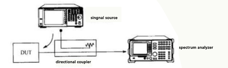
The directional coupler is used for anti-interference measurement of receiver or spurious height of cellular phone.
In this test circuit, the directivity of the directional coupler is very important. The spectrum analyzer connected to the through end only wants to receive the signal from the DUT and does not want to receive the password from the coupling end.
3, for signal sampling and monitoring
Transmitter online measurement and monitoring may be one of the most widely used applications of directional couplers. The following figure is a typical application of directional couplers for cellular base station measurement. Suppose the transmitter’s output power is 43dBm (20W), the coupling of the directional coupler. The capacity is 30dB, the insertion loss (line loss plus coupling loss) is 0.15dB. The coupling end has 13dBm (20mW) signal sent to the base station tester, the direct output of the directional coupler is 42.85dBm (19.3W), and the leakage is The power on the isolated side is absorbed by a load.
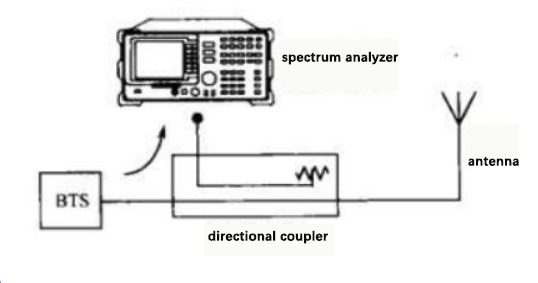
The directional coupler is used for base station measurement.
Almost all transmitters use this method for online sampling and monitoring, and perhaps only this method can guarantee the performance test of the transmitter under normal working conditions. But it should be noted that the same is the transmitter test, and different testers have different concerns. Taking WCDMA base stations as an example, operators must pay attention to the indicators in their working frequency band (2110~2170MHz), such as signal quality, in-channel power, adjacent channel power, etc. Under this premise, manufacturers will install at the output end of the base station A narrowband (such as 2110~2170MHz) directional coupler to monitor the transmitter’s in-band working conditions and send it to the control center at any time.
If it is the regulator of the radio frequency spectrum-the radio monitoring station to test the soft base station indicators, its focus is entirely different. According to the radio management specification requirements, the test frequency range is extended to 9kHz~12.75GHz, and the tested base station is so broad. How much spurious radiation will be generated in the frequency band and interfere with the regular operation of other base stations? A concern of radio monitoring stations. At this time, a directional coupler with the same bandwidth is required for signal sampling, but a directional coupler that can cover 9kHz~12.75GHz does not seem to exist. We know that the length of the coupling arm of a directional coupler is related to its center frequency. The bandwidth of an ultra-wideband directional coupler can achieve 5-6 octave bands, such as 0.5-18GHz, but the frequency band below 500MHz cannot be covered.
4, online power measurement
In the through-type power measurement technology, the directional coupler is a very critical device. The following figure shows the schematic diagram of a typical pass-through high-power measurement system. The forward power from the amplifier under Test is sampled by the forward coupling end (terminal 3) of the directional coupler and sent to the power meter. The reflected power is sampled by the reverse coupling terminal (terminal 4) and sent to the power meter.
A directional coupler is used for high power measurement.
Please note: In addition to receiving the reflected power from the load, the reverse coupling terminal (terminal 4) also receives leakage power from the forward direction (terminal 1), which is caused by the directivity of the directional coupler. The reflected energy is what the tester hopes to measure, and the leakage power is the primary source of errors in the reflected power measurement. The reflected power and leakage power are superimposed on the reverse coupling end (4 ends) and then sent to the power meter. Since the transmission paths of the two signals are different, it is a vector superposition. If the leakage power input to the power meter can be Compared with the reflected power, it will produce a significant measurement error.
Of course, the reflected power from the load (end 2) will also leak to the forward coupling end (end 1, not shown in the figure above). Still, its magnitude is minimal compared to the forward power, which measures forward strength. The resulting error can be ignored.
Beijing Rofea Optoelectronics Co., Ltd. located in China’s “Silicon Valley” – Beijing Zhongguancun, is a high-tech enterprise dedicated to serving domestic and foreign research institutions, research institutes, universities and enterprise scientific research personnel. Our company is mainly engaged in the independent research and development, design, manufacturing, sales of optoelectronic products, and provides innovative solutions and professional, personalized services for scientific researchers and industrial engineers. After years of independent innovation, it has formed a rich and perfect series of photoelectric products, which are widely used in municipal, military, transportation, electric power, finance, education, medical and other industries.
We are looking forward to cooperation with you!
Post time: Apr-20-2023