


Microwave optoelectronics, as the name suggests, is the intersection of microwave and optoelectronics. Microwaves and light waves are electromagnetic waves, and the frequencies are many orders of magnitude different, and the components and technologies developed in their respective fields are very different. In combination, we can take advantage of each other, but we can get new applications and characteristics that are difficult to realize respectively.
Optical communication is a prime example of the combination of microwaves and photoelectrons. Early telephone and telegraph wireless communications, the generation, propagation and reception of signals, all used microwave devices. Low frequency electromagnetic waves are used initially because the frequency range is small and the channel capacity for transmission is small. The solution is to increase the frequency of the transmitted signal, the higher the frequency, the more spectrum resources. But the high frequency signal in the air propagation loss is large, but also easy to be blocked by obstacles. If the cable is used, the loss of the cable is large, and long-distance transmission is a problem. The emergence of optical fiber communication is a good solution to these problems. Optical fiber has very low transmission loss and is an excellent carrier for transmitting signals over long distances. The frequency range of light waves is much greater than that of microwaves and can transmit many different channels simultaneously. Because of these advantages of optical transmission, optical fiber communication has become the backbone of today’s information transmission.
Optical communication has a long history, research and application are very extensive and mature, here is not to say more. This paper mainly introduces the new research content of microwave optoelectronics in recent years other than optical communication. Microwave optoelectronics mainly uses the methods and technologies in the field of optoelectronics as the carrier to improve and achieve the performance and application that are difficult to achieve with traditional microwave electronic components. From the perspective of application, it mainly includes the following three aspects.
The first is the use of optoelectronics to generate high-performance, low-noise microwave signals, from the X-band all the way to the THz band.
Second, microwave signal processing. Including delay, filtering, frequency conversion, receiving and so on.
Third, the transmission of analog signals.
In this article, the author only introduces the first part, the generation of microwave signal. Traditional microwave millimeter wave is mainly generated by iii_V microelectronic components. Its limitations have the following points: First, to high frequencies such as 100GHz above, traditional microelectronics can produce less and less power, to the higher frequency THz signal, they can do nothing. Second, in order to reduce phase noise and improve frequency stability, the original device needs to be placed in an extremely low temperature environment. Third, it is difficult to achieve a wide range of frequency modulation frequency conversion. To solve these problems, optoelectronic technology can play a role. The main methods are described below.
1. Through the difference frequency of two different frequency laser signals, a high-frequency photodetector is used to convert microwave signals, as shown in Figure 1.
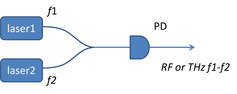
Figure 1. Schematic diagram of microwaves generated by the difference frequency of two lasers.
The advantages of this method are simple structure, can generate extremely high frequency millimeter wave and even THz frequency signal, and by adjusting the frequency of the laser can carry out a large range of fast frequency conversion, sweep frequency. The disadvantage is that the linewidth or phase noise of the difference frequency signal generated by two unrelated laser signals is relatively large, and the frequency stability is not high, especially if a semiconductor laser with a small volume but a large linewidth (~MHz) is used. If the system weight volume requirements are not high, you can use low noise (~kHz) solid-state lasers, fiber lasers, external cavity semiconductor lasers, etc. In addition, two different modes of laser signals generated in the same laser cavity can also be used to generate a difference frequency, so that the microwave frequency stability performance is greatly improved.
2. In order to solve the problem that the two lasers in the previous method are incoherent and the signal phase noise generated is too large, the coherence between the two lasers can be obtained by the injection frequency locking phase locking method or the negative feedback phase locking circuit. Figure 2 shows a typical application of injection locking to generate microwave multiples (Figure 2). By directly injecting high frequency current signals into a semiconductor laser, or by using a LinBO3-phase modulator, multiple optical signals of different frequencies with equal frequency spacing can be generated, or optical frequency combs. Of course, the commonly used method to obtain a wide spectrum optical frequency comb is to use a mode-locked laser. Any two comb signals in the generated optical frequency comb are selected by filtering and injected into laser 1 and 2 respectively to realize frequency and phase locking respectively. Because the phase between the different comb signals of the optical frequency comb is relatively stable, so that the relative phase between the two lasers is stable, and then by the method of difference frequency as described before, the multi-fold frequency microwave signal of the optical frequency comb repetition rate can be obtained.
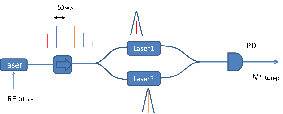
Figure 2. Schematic diagram of microwave frequency doubling signal generated by injection frequency locking.
Another way to reduce the relative phase noise of the two lasers is to use a negative feedback optical PLL, as shown in Figure 3.
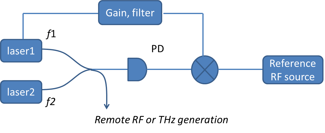
Figure 3. Schematic diagram of OPL.
The principle of optical PLL is similar to that of PLL in the field of electronics. The phase difference of the two lasers is converted into an electrical signal by a photodetector (equivalent to a phase detector), and then the phase difference between the two lasers is obtained by making a difference frequency with a reference microwave signal source, which is amplified and filtered and then fed back to the frequency control unit of one of the lasers (for semiconductor lasers, it is the injection current). Through such a negative feedback control loop, the relative frequency phase between the two laser signals is locked to the reference microwave signal. The combined optical signal can then be transmitted through optical fibers to a photodetector elsewhere and converted into a microwave signal. The resulting phase noise of the microwave signal is almost the same as that of the reference signal within the bandwidth of the phase-locked negative feedback loop. The phase noise outside the bandwidth is equal to the relative phase noise of the original two unrelated lasers.
In addition, the reference microwave signal source can also be converted by other signal sources through frequency doubling, divisor frequency, or other frequency processing, so that the lower frequency microwave signal can be multidoubled, or converted to high-frequency RF, THz signals.
Compared to injection frequency locking can only obtain frequency doubling, phase-locked loops are more flexible, can produce almost arbitrary frequencies, and of course more complex. For example, the optical frequency comb generated by the photoelectric modulator in Figure 2 is used as the light source, and the optical phase-locked loop is used to selectively lock the frequency of the two lasers to the two optical comb signals, and then generate high-frequency signals through the difference frequency, as shown in Figure 4. f1 and f2 are the reference signal frequencies of the two PLLS respectively, and a microwave signal of N*frep+f1+f2 can be generated by the difference frequency between the two lasers.
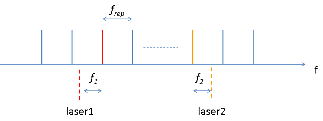
Figure 4. Schematic diagram of generating arbitrary frequencies using optical frequency combs and PLLS.
3. Use mode-locked pulse laser to convert optical pulse signal into microwave signal through photodetector.
The main advantage of this method is that a signal with very good frequency stability and very low phase noise can be obtained. By locking the frequency of the laser to a very stable atomic and molecular transition spectrum, or an extremely stable optical cavity, and the use of self-doubling frequency elimination system frequency shift and other technologies, we can obtain a very stable optical pulse signal with a very stable repetition frequency, so as to obtain a microwave signal with ultra-low phase noise. Figure 5.
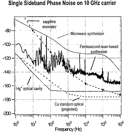
Figure 5. Comparison of relative phase noise of different signal sources.
However, because the pulse repetition rate is inversely proportional to the cavity length of the laser, and the traditional mode-locked laser is large, it is difficult to obtain high frequency microwave signals directly. In addition, the size, weight and energy consumption of traditional pulsed lasers, as well as the harsh environmental requirements, limit their mainly laboratory applications. To overcome these difficulties, research has recently begun in the United States and Germany using nonlinear effects to generate frequency-stable optical combs in very small, high-quality chirp mode optical cavities, which in turn generate high-frequency low-noise microwave signals.
4. opto electronic oscillator, Figure 6.
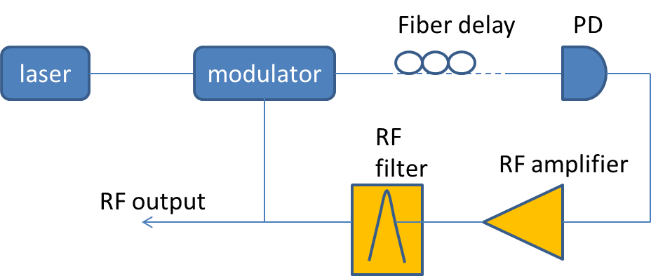
Figure 6. Schematic diagram of photoelectric coupled oscillator.
One of the traditional methods of generating microwaves or lasers is to use a self-feedback closed loop, as long as the gain in the closed loop is greater than the loss, the self-excited oscillation can produce microwaves or lasers. The higher the quality factor Q of the closed loop, the smaller the generated signal phase or frequency noise. In order to increase the quality factor of the loop, the direct way is to increase the loop length and minimize the propagation loss. However, a longer loop can usually support the generation of multiple modes of oscillation, and if a narrow-bandwidth filter is added, a single-frequency low-noise microwave oscillation signal can be obtained. Photoelectric coupled oscillator is a microwave signal source based on this idea, it makes full use of the fiber’s low propagation loss characteristics, using a longer fiber to improve the loop Q value, can produce a microwave signal with very low phase noise. Since the method was proposed in the 1990s, this type of oscillator has received extensive research and considerable development, and there are currently commercial photoelectric coupled oscillators. More recently, photoelectric oscillators whose frequencies can be adjusted over a wide range have been developed. The main problem of microwave signal sources based on this architecture is that the loop is long, and the noise in its free flow (FSR) and its double frequency will be significantly increased. In addition, the photoelectric components used are more, the cost is high, the volume is difficult to reduce, and the longer fiber is more sensitive to environmental disturbance.
The above briefly introduces several methods of photoelectron generation of microwave signals, as well as their advantages and disadvantages. Finally, the use of photoelectrons to produce microwave has another advantage is that the optical signal can be distributed through the optical fiber with very low loss, long-distance transmission to each use terminal and then converted into microwave signals, and the ability to resist electromagnetic interference is significantly improved than traditional electronic components.
The writing of this article is mainly for reference, and combined with the author’s own research experience and experience in this field, there are inaccuracies and incomprehensiveness, please understand.
Post time: Jan-03-2024