


Learn laser alignment techniques
Ensuring the alignment of the laser beam is the primary task of the alignment process. This may require the use of additional optics such as lenses or fiber collimators, especially for diode or fiber laser sources. Prior to laser alignment, you must be familiar with laser safety procedures and ensure that you are equipped with safety glasses suitable for blocking laser wavelengths. In addition, for invisible lasers, detection cards may be needed to aid alignment efforts.
In the laser alignment, the Angle and position of the beam need to be controlled simultaneously. This can require the use of multiple optics, add complexity to alignment Settings, and can take up a lot of desktop space. However, with kinematic mounts, a simple and effective solution can be adopted, especially for space-constrained applications.
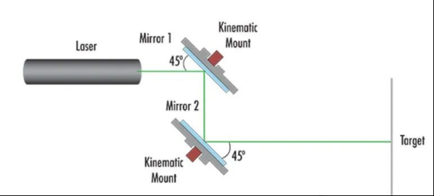
Figure 1: Parallel (Z-fold) structure
Figure 1 shows the basic setup of the Z-Fold structure and shows the reason behind the name. The two mirrors mounted on two kinematic mounts are used for angular displacement and are positioned so that the incident light beam hits the mirror surface of each mirror at the same Angle. To simplify the setup, place the two mirrors at about 45°. In this setup, the first kinematic support is used to obtain the desired vertical and horizontal position of the beam, while the second support is used to compensate for the Angle. The Z-Fold structure is the preferred method for aiming multiple laser beams at the same target. When combining lasers with different wavelengths, one or more mirrors may need to be replaced with dichroic filters.
To minimize duplication in the alignment process, the laser can be aligned at two separate reference points. A simple crosshair or a white card marked with an X are very useful tools. First, set the first reference point on or near the surface of mirror 2, as close to the target as possible. The second point of reference is the goal itself. Use the first kinematic stand to adjust the horizontal (X) and vertical (Y) positions of the beam at the initial reference point so that it matches the desired position of the target. Once this position is reached, a second kinematic bracket is used to adjust the angular offset, aiming the laser beam at the actual target. The first mirror is used to approximate the desired alignment, while the second mirror is used to fine-tune the alignment of the second reference point or target.
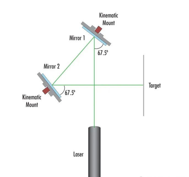
figure 2: Vertical (Figure-4) structure
The figure-4 structure is more complex than the Z-Fold, but can provide a more compact system layout. Similar to the Z-Fold structure, the figure-4 layout uses two mirrors mounted on moving brackets. However, unlike the Z-Fold structure, the mirror is mounted at a 67.5° Angle, which forms a “4″ shape with the laser beam (Figure 2). This setup allows the reflector 2 to be placed away from the source laser beam path. As with the Z-Fold configuration, the laser beam should be aligned at two reference points, the first reference point at mirror 2 and the second at the target. The first kinematic bracket is applied to move the laser point to the desired XY position on the surface of the second mirror. A second kinematic bracket should then be used to compensate for angular displacement and fine-tune alignment on the target.
Regardless of which of the two configurations are used, following the above procedure should minimize the number of iterations required to achieve the desired result. With the right tools and equipment and a few simple tips, laser alignment can be greatly simplified.
Post time: Mar-11-2024