


Ultra Compact IQ Modulator Bias Controller Automatic Bias Controller


Feature
•Provides three biases for IQ modulators Modulation format independent:
•QPSK, QAM, OFDM, SSB verified
•Plug and Play:
No manual calibration needed Everything automatic
•I, Q arms: controll on Peak and Null modes High extinction ratio: 50dB max1
•P arm: controll on Q+ and Q- modes Accuracy: ± 2◦
•Low profile: 40mm(W) × 28mm(D) × 8mm(H)
•High stability: fully digital implementation Easy to use:
•Manual operation with mini jumper Flexible OEM operations through UART2
•Two modes to provide bias voltages: a.Automatic Bias Control b.User defined bias voltage
Application
•LiNbO3 and other IQmodulators
•QPSK, QAM, OFDM, SSB and etc
•Coherent Transmission
Performance
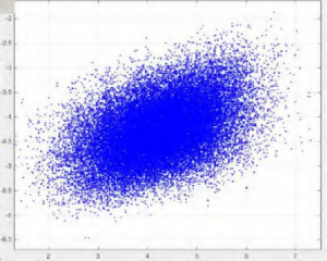
Figure 1. Constellation (without controller)
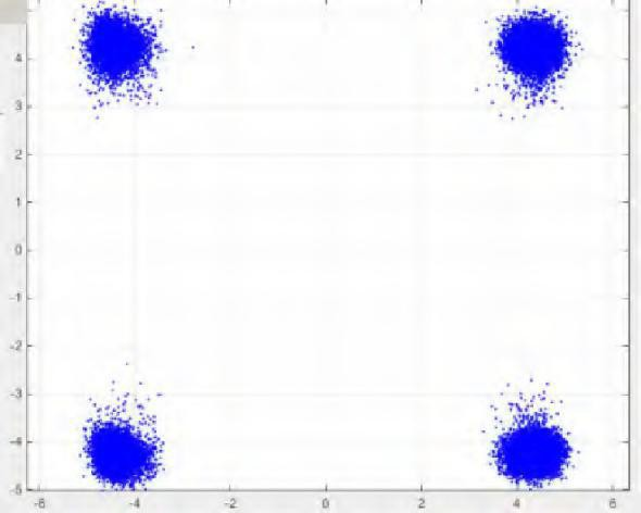
Figure 2. QPSK Constellation(with controller
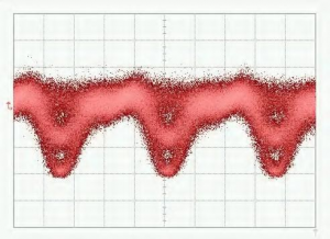
Figure 3. QPSK-Eye pattern
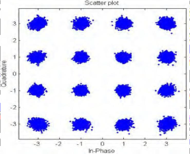
Figure 5. 16-QAM Constellation pattern
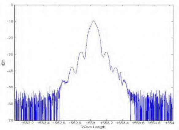
Figure 4. QPSK Spectrum
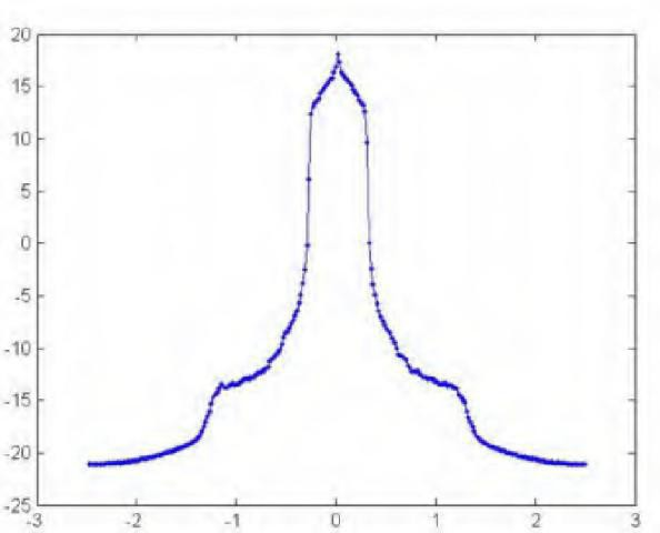
Figure 6. 16-QAM Spectrum
Specifications
|
Parameter |
Min |
Typ |
Max |
Unit |
| Controll Performance | ||||
| I, Q arms are controlled on Null(Minimum) or Peak(Maximum) point | ||||
| Extinction ratio |
MER1 |
50 |
dB |
|
| P arm is controlled on Q+(right quadrature) or Q-( left quadrature) point | ||||
| Accuracy at Quad |
−2 |
+2 |
degree2 |
|
| Stablization time |
15 |
20 |
25 |
s |
| Electrical | ||||
| Positive power voltage |
+14.5 |
+15 |
+15.5 |
V |
| Positive power current |
20 |
30 |
mA |
|
| Negative power voltage |
-15.5 |
-15 |
-14.5 |
V |
| Negative power current |
8 |
15 |
mA |
|
| Output voltage range |
-14.5 |
+14.5 |
V |
|
| Dither amplitude |
1%Vπ |
V |
||
| Optical | ||||
| Input optical power3 |
-30 |
-8 |
dBm |
|
| Input wavelength |
1100 |
1650 |
nm |
|
1. MER refers to Modulator Extinction Ratio. The extinction ratio achieved is typically the extinction ratio of modulator specified in modulator datasheet.
2. Please be noted that input optical power does not correspond to the optical power at selected bias point. It refers to the maximum optical power that the modulator can export to controller when bias voltage ranges from −Vπ to +Vπ .
User Interface
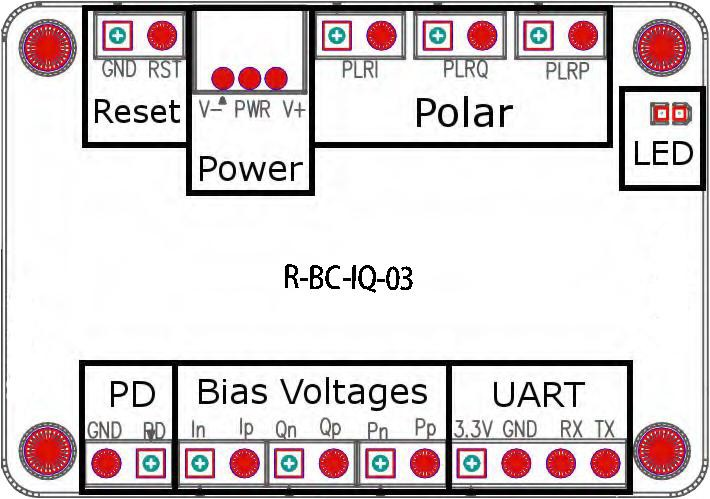
Figure5. Assembly
| Group | Operation |
Explanation |
| Reset | Insert jumper and pull out after 1 second | Reset the controller |
| Power | Power source for bias controller | V- connects the negative electrode of the power supply |
| V+ connects the positive electrode of the power supply | ||
| Middle port connects with the ground electrode | ||
| Polar1 | PLRI: Insert or pull out the jumper | no jumper: Null mode; with jumper: Peak mode |
| PLRQ: Insert or pull out the jumper | no jumper: Null mode; with jumper: Peak mode | |
| PLRP: Insert or pull out the jumper | no jumper: Q+ mode; with jumper: Q- mode | |
| LED | Constantly on | Working under stable state |
| On-off or off-on every 0.2s | Processing data and searching for controlling point | |
| On-off or off-on every 1s | Input optical power is too weak | |
| On-off or off-on every 3s | Input optical power is too strong | |
| PD 2 | Connect with the photodiode | PD port connects the Cathode of the photodiode |
| GND port connects the Anode of the photodiode | ||
| Bias Voltages | In, Ip: Bias voltage for I arm | Ip: Positive side; In: Negative side or ground |
| Qn, Qp: Bias voltage for Q arm | Qp: Positive side; Qn: Negative side or ground | |
| Pn, Pp: Bias voltage for P arm | Pp: Positive side; Pn: Negative side or ground | |
| UART | Operate controller via UART | 3.3: 3.3V reference voltage |
| GND: Ground | ||
| RX: Receive of controller | ||
| TX: Transmit of controller |
1 Polar depends on system RF signal. When there is no RF signal in the system, the polar should be positive. When RF signal has amplitude greater than a certain level, the polar will change from positive into negative. At this time, Null point and Peak point will switch with each other.Q+ point and Q- point will switch with each other as well.Polar switch enables user to change the polar
directly without changing operation points.
2 Only one choice shall be chosen between using controller photodiode or using modulator photodiode. It is recommended to use controller photodiode for Lab experiments for two reasons. Firstly, controller photodiode has ensured qualities. Secondly, it is easier to adjust the input light intensity.If using modulator’s internal photodiode, please make sure that the output current of photodiode is strictly proportional to input power.
Rofea Optoelectronics offers a product line of commercial Electro-optic modulators, Phase modulators, Intensity modulator, Photodetectors, Laser light sources, DFB lasers,Optical amplifiers, EDFA, SLD laser, QPSK modulation, Pulse laser, Light detector, Balanced photodetector, Laser driver, Fiber optic amplifier, Optical power meter, Broadband laser, Tunable laser, Optical detector, Laser diode driver, Fiber amplifier. We also provide many particular modulators for customization, such as 1*4 array phase modulators, ultra-low Vpi, and ultra-high extinction ratio modulators, primarily used in universities and institutes.
Hope our products will be helpful to you and your research.


